

This sponsored article is delivered to you by COMSOL.
“Legal guidelines, Whitehouse acquired 5 minutes sign. Coil indicators too weak to relay. Strive drive sluggish and common. I’ve put intermediate pulley. Reply by coils.”
Sound acquainted? The message above was despatched by means of the primary transatlantic telegraph cable between Newfoundland and Eire, manner again in 1858. (“Whitehouse” refers back to the chief electrician of the Atlantic Telegraph Firm on the time, Wildman Whitehouse.) Quick ahead to 2014: The underside of the ocean is dwelling to almost 300 communications cables, connecting nations and offering web communications world wide. Quick ahead once more: As of 2021, there are an estimated 1.3 million km of submarine cables (Determine 1) in service, starting from a brief 131 km cable between Eire and the U.Okay. to the 20,000 km cable that connects Asia with North America and South America. We all know what the world of submarine cables seems like at the moment, however what in regards to the future?
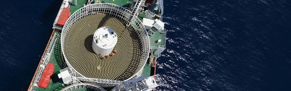
Determine 1. Submarine cables hold the world related.
Transferring Wind Energy Offshore
The offshore wind (OFW) trade is without doubt one of the most quickly advancing sources of energy world wide. It is smart: Wind is stronger and extra constant over the open ocean than it’s on land. Some wind farms are able to powering 500,000 houses or extra. At present, Europe leads the market, making up virtually 80 % of OFW capability. Nonetheless, the worldwide demand for vitality is predicted to extend by 20 % in 10 years, with a big majority of that demand equipped by sustainable vitality sources like wind energy.
Offshore wind farms (Determine 2) are made up of networks of generators. These networks embody cables that join wind farms to the shore and provide electrical energy to our energy grid infrastructure (Determine 3). Many OFW farms are made up of grounded constructions, like monopiles and different forms of bottom-fixed wind generators. The foundations for these constructions are costly to assemble and troublesome to put in in deep sea environments, because the cables must be buried within the seafloor. Set up and upkeep is less complicated to perform in shallow waters.
Wind generators for offshore wind farms are beginning to be constructed additional out into the ocean. This creates a brand new want for well-designed subsea cables that may attain longer distances, survive in deeper waters, and higher join our world with sustainable energy.
The way forward for offshore wind lies in wind farms that float on ballasts and moorings, with the cables laid instantly on the seafloor. Floating wind farms are an amazing answer when wind farms located simply off the coast develop crowded. They’ll additionally reap the benefits of the larger and extra highly effective winds that happen additional out to sea. Floating wind farms are anticipated to develop extra standard over the subsequent decade. That is an particularly engaging possibility for areas just like the Pacific Coast of america and the Mediterranean, the place the shores are deeper, versus the shallow waters of the Atlantic Coast of the U.S., U.Okay., and Norway. One necessary requirement of floating OFW farms is the set up of dynamic, high-capacity submarine cables which are capable of successfully harness and ship the generated electrical energy to our shores.
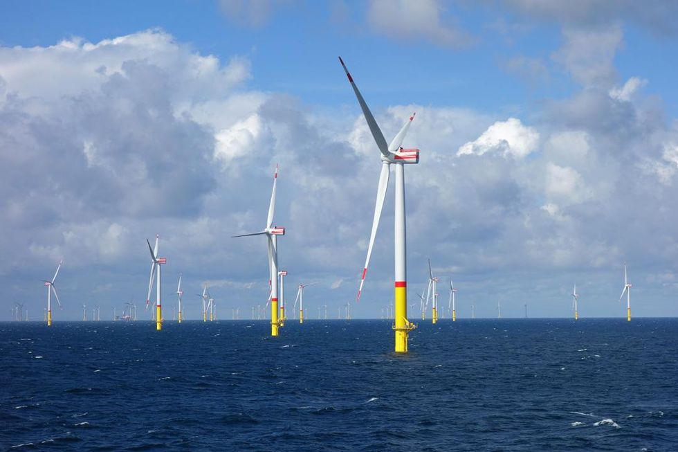
Determine 2. Offshore wind farms are anticipated to assist meet rising calls for for sustainable vitality.
Picture by Ein Dahmer — Personal work. Licensed below CC BY-SA 4.0, by way of Wikimedia Commons
Design Components for Resilient Subsea Cables
Ever skilled slower than normal web? Failure of a subsea cable could also be in charge. Cable failures of this sort are a standard — and costly — incidence, whether or not from the harm of mechanical stress and pressure brought on by bedrock, fishing trawlers, anchors, and issues with the cable design itself. Because the offshore wind trade continues to develop, our have to develop energy cables that may safely and effectively join these farms to our energy grid grows as nicely.
Earlier than fixing or putting in a submarine cable, which may value billions of {dollars}, cable designers have to make sure that designs will carry out as supposed in undersea situations. At this time, that is usually achieved with the assistance of computational electromagnetics modeling. To validate cable simulation outcomes, worldwide requirements are used, however these requirements haven’t been capable of sustain with current developments in computational energy and the simulation software program’s rising capabilities. Hellenic Cables, together with its subsidiary FULGOR, use the finite component technique (FEM) to research their cable designs and evaluate them to experimental measurements, typically getting higher outcomes than what the worldwide requirements can provide.
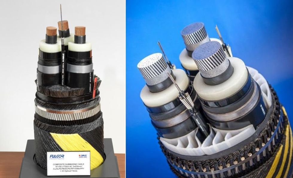
Determine 3. Examples of three-core (3C) submarine cables accessible from Hellenic Cables.
Up to date Methodology for Calculating Cable Losses
The Worldwide Electrotechnical Fee (IEC) offers requirements for electrical cables, together with Normal 60287 1-1 for calculating cable losses and present rankings. One downside with the formulation utilized in Normal 60287 is that it overestimates cable losses — particularly the losses within the armor of three-core (3C) submarine cables. Cable designers are pressured to undertake a brand new methodology for performing these analyses, and the crew at Hellenic Cables acknowledges this. “With a extra correct and practical mannequin, vital optimization margins are anticipated,” says Dimitrios Chatzipetros, crew chief of the Numerical Evaluation group at Hellenic Cables. The brand new methodology will allow engineers to cut back cable cross sections, thereby decreasing their prices, which is the paramount objective for cable manufacturing.
An electrical cable is a fancy machine to mannequin. The geometric construction consists of three principal energy cores which are helically twisted with a selected lay size, and lots of of extra wires — display or armor wires — which are twisted with a second or third lay size. This makes it troublesome to generate the mesh and resolve for the electromagnetic fields. “This can be a tedious 3D downside with difficult materials properties, as a result of a few of the components are ferromagnetic,” says Andreas Chrysochos, affiliate principal engineer within the R&D division of Hellenic Cables.
Lately, FEM has made a large leap in the case of cable evaluation. The Hellenic Cables crew first used FEM to mannequin a full cable part of round 30 to 40 meters in size. This turned out to be an enormous numerical problem that may solely realistically be solved on a supercomputer. By switching to periodic fashions with a periodic size equal to the cable’s cross pitch, the crew decreased the issue from 40 meters right down to 2–4 meters. Then they launched short-twisted periodicity, which reduces the periodic size of the mannequin from meters to centimeters, making it a lot lighter to unravel. “The progress was super,” says Chrysochos. (Determine 4)
Though the enhancements that FEM brings to cable evaluation are nice, Hellenic Cables nonetheless must persuade its purchasers that their validated outcomes are extra practical than these supplied by the present IEC customary. Purchasers are sometimes already conscious of the truth that IEC 60287 overestimates cable losses, however outcomes visualization and comparability to precise measurements can construct confidence in mission stakeholders. (Determine 5)
Finite Factor Modeling of Cable Methods
Electromagnetic interference (EMI) presents a number of challenges in the case of designing cable methods — particularly the capacitive and inductive couplings between cable conductors and sheaths. For one, when calculating present rankings, engineers have to account for energy losses within the cable sheaths throughout regular operation. As well as, the overvoltages on cable sheaths must be inside acceptable limits to fulfill typical well being and security requirements.
As Chrysochos et al. talk about in “Capacitive and Inductive Coupling in Cable Methods – Comparative Research between Calculation Strategies” (Ref. 3), there are three principal approaches in the case of calculating these capacitive and inductive couplings. The primary is the advanced impedance technique (CIM), which calculates the cable system’s currents and voltages whereas neglecting its capacitive currents. This technique additionally assumes that the earth return path is represented by an equal conductor. One other widespread technique is electromagnetic transients program (EMT) software program, which can be utilized to research electromagnetic transients in energy methods utilizing each time- and frequency-domain fashions.
The third technique, FEM, is the muse of the COMSOL Multiphysics software program. The Hellenic Cables crew used COMSOL Multiphysics and the add-on AC/DC Module to compute the electrical fields, currents, and potential distribution in conducting media. “The AC/DC Module and solvers behind it are very sturdy and environment friendly for some of these issues,” says Chrysochos.
The Hellenic Cables crew in contrast the three strategies — CIM, EMT software program, and FEM (with COMSOL Multiphysics) — when analyzing an underground cable system with an 87/150 kV nominal voltage and 1000 mm2 cross part (Determine 6). They modeled the magnetic subject and induced present density distributions in and across the cable system’s conductors, accounting for the bonding sort with an exterior electrical circuit. The outcomes between all three strategies present good settlement for the cable system for 3 completely different configurations: strong bonding, single-point bonding, and cross bonding (Determine 7). This demonstrates that FEM will be utilized to all forms of cable configurations and installations when considering each capacitive and inductive coupling.
The Hellenic Cables crew additionally used FEM to check thermal results in subsea cables, equivalent to HVAC submarine cables for offshore wind farms, as described in “Assessment of the Accuracy of Single Core Equal Thermal Mannequin for Offshore Wind Farm Cables” (Ref. 4). The present IEC Normal 60287 1-1 features a thermal mannequin, and the crew used FEM to determine its weak spots and enhance its accuracy. First, they validated the present IEC mannequin with finite component evaluation. They discovered that the present requirements don’t account for the thermal impression of the cable system’s metallic display supplies, which implies that the temperature will be underestimated by as much as 8°C. Deriving analytical, correcting formulation based mostly on a number of FEM fashions, the crew decreased this discrepancy to 1°C! Their evaluation additionally highlights vital discrepancies between the usual and the FEM mannequin, particularly when the corresponding sheath thickness is small, the sheath thermal conductivity is excessive, and the ability core is giant. This concern is especially necessary for OFW tasks, because the cables concerned are anticipated to develop bigger and bigger.
Additional Analysis into Cable Designs
Along with finding out inductive and capacitive coupling and thermal results, the Hellenic Cables crew evaluated different features of cable system designs, together with losses, thermal resistance of surrounding soil, and grounding resistance, utilizing FEM and COMSOL Multiphysics. “Usually, COMSOL Multiphysics is far more person pleasant and environment friendly, equivalent to when introducing temperature-dependent losses within the cable, or when presenting semi-infinite soil and infinite component domains. We discovered a number of methods to confirm what we already learn about cables, their thermal efficiency, and loss calculation,” says Chatzipetros.
Losses
The conductor measurement of a subsea or terrestrial cable impacts the price of the cable system. That is typically a vital facet of an offshore wind farm mission. To optimize the conductor measurement, designers want to have the ability to precisely decide the cable’s losses. To take action, they first turned to temperature. Currents induced in a cable’s magnetic sheaths yield additional losses, which contribute to the temperature rise of the conductor.
When calculating cable losses, the present IEC customary doesn’t contemplate proximity results in sheath losses. If cable cores are in shut proximity (say, for a wind farm 3C cable), the accuracy of the loss calculation is decreased. Utilizing FEM, the Hellenic Cables crew was capable of examine how conductor proximity results affect losses generated in sheaths in submarine cables with lead-sheathed cores and a nonmagnetic armor. They then in contrast the IEC customary with the outcomes from the finite component evaluation, which confirmed higher settlement with measured values from an experimental setup (Determine 8). This analysis was mentioned within the paper “Induced Losses in Non-Magnetically Armoured HVAC Windfarm Export Cables” (Ref. 5).
Thermal Resistance of Soil
Completely different soil varieties have completely different thermal insulating traits, which may severely restrict the quantity of warmth dissipated from the cable, thereby decreasing its current-carrying capability. Which means that bigger conductor sizes are wanted to transmit the identical quantity of energy in areas with extra thermally adversarial soil, inflicting the cable’s value to extend.
Within the paper “Rigorous calculation of exterior thermal resistance in non-uniform soils” (Ref. 6), the Hellenic Cables crew used FEM to calculate the efficient soil thermal resistance for various cable varieties and cable set up eventualities (Determine 9). First, they solved for the warmth switch downside below steady-state situations with arbitrary temperatures on the cable and soil surfaces. They then evaluated the efficient thermal resistance based mostly on the warmth dissipated by the cable floor into the encircling soil.
Simulations have been carried out for 2 forms of cables: a typical SL-type submarine cable with 87/150 kV, a 1000 mm2 cross part, and copper conductors, in addition to a typical terrestrial cable with 87/150 kV, a 1200 mm2 cross part, and aluminum conductors. The crew analyzed three completely different cable set up eventualities (Determine 10).
The primary state of affairs is when a cable is put in beneath a horizontal layer, equivalent to when sand waves are anticipated to progressively add to the seafloor’s preliminary stage after set up. The second is when a cable is put in inside a horizontal layer, which happens when the set up takes place in a area with horizontal directional drilling (HDD). The third state of affairs is when a cable is put in inside a backfilled trench, typical for areas with unfavorable thermal habits, in an effort to cut back the impression of the soil on the temperature rise of the cable. The numerical modeling outcomes show that FEM will be utilized to any materials or form of multilayer or backfilled soil, and that the strategy is appropriate with the present score methodology in IEC Normal 60287.
Grounding Resistance
The analysis of grounding resistance is necessary to make sure the integrity and safe operation of cable sheath voltage limiters (SVLs) when topic to earth potential rise (EPR). As a way to calculate grounding resistance, engineers have to know the soil resistivity for the issue at hand and have a sturdy calculation technique, like FEM.
The Hellenic Cables crew used FEM to research soil resistivity for 2 websites: one in northern Germany and one in southern Greece. As described within the paper “Analysis of Grounding Resistance and Its Impact on Underground Cable Methods” (Ref. 7), they discovered that the obvious resistivity of the soil is a monotonic operate of distance, and {that a} two-layer soil mannequin is ample for his or her modeling downside (Determine 11). After discovering the resistivity, the crew calculated the grounding resistance for a single-rod state of affairs (as a method of validation). After that, they proceeded with a fancy grid, which is typical of cable joint pits present in OWFs. For each eventualities, they discovered the EPR on the substations and transition joint pit, in addition to the utmost voltage between the cable sheath and native earth (Determine 12). The outcomes reveal that FEM is a extremely correct calculation technique for grounding resistance, as they present good settlement with each numerical information from measurements and electromagnetic transient software program calculations (Determine 13).
A Shiny and Windy Future
The Hellenic Cables crew plans to proceed the necessary work of additional bettering the entire cable fashions they’ve developed. The crew has additionally carried out analysis into HVDC cables, which contain XLPE insulation and voltage supply converter (VSC) know-how. HVDC cables will be extra value environment friendly for methods put in over lengthy distances.
Just like the wind used to energy offshore wind farms, electrical cable methods are throughout us. Despite the fact that we can’t at all times see them, they’re working onerous to make sure we’ve got entry to a high-powered and well-connected world. Optimizing the designs of subsea and terrestrial cables is a vital a part of constructing a sustainable future.
References
- M. Hatlo, E. Olsen, R. Stølan, J. Karlstrand, “Correct analytic components for calculation of losses in three-core submarine cables,” Jicable, 2015.
- S. Sturm, A. Küchler, J. Paulus, R. Stølan, F. Berger, “3D-FEM modelling of losses in armoured submarine energy cables and comparability with measurements,” CIGRE Session 48, 2020.
- A.I. Chrysochos et al., “Capacitive and Inductive Coupling in Cable Methods – Comparative Research between Calculation Strategies”, tenth Worldwide Convention on Insulated Energy Cables, Jicable, 2019.
- D. Chatzipetros and J.A. Pilgrim, “Assessment of the Accuracy of Single Core Equal Thermal Mannequin for Offshore Wind Farm Cables”, IEEE Transactions on Energy Supply, Vol. 33, No. 4, pp. 1913–1921, 2018.
- D. Chatzipetros and J.A. Pilgrim, “Induced Losses in Non-Magnetically Armoured HVAC Windfarm Export Cables”, IEEE Worldwide Convention on Excessive Voltage Engineering and Utility (ICHVE), 2018.
- A.I. Chrysochos et al., “Rigorous calculation of exterior thermal resistance in non-uniform soils”, Cigré Session 48, 2020.
- A.I. Chrysochos et al., “Analysis of Grounding Resistance and Its Impact on Underground Cable Methods”, Mediterranean Convention on Energy Era, Transmission , Distribution and Vitality Conversion, 2020.